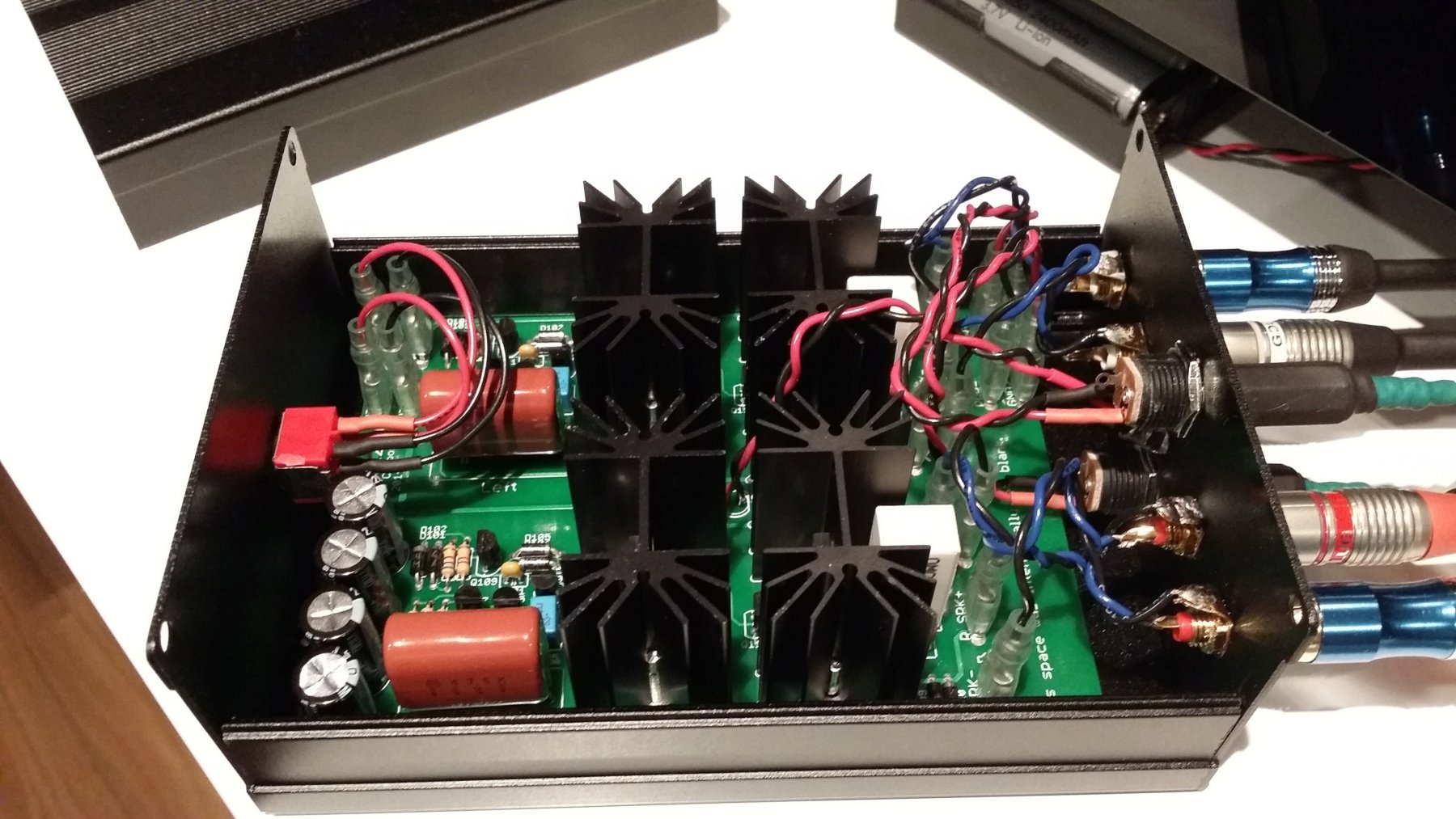
I’m back with another amplifier project, but this time it’s kinda like a remake instead of a completely new amp. The story behind this project started 4 days after I completed the Mini6.
While I was drilling the holes for the jacks on the Mini6, I accidentally put too much pressure on the acrylic enclosure and it cracked, it was very small crack, practically impossible to see, between the two RCA jacks on the front, but after using it for a while and noticing how the crack would open a little bit every time I plugged something in, I decided to fix it using super glue (facepalm) and while I was using the glue I didn’t notice that one small drop fell in the PCB. I put everything back together and tested, it sounded horrible and when I looked inside I could see the stain of the glue which was destroying the sensitive part of the circuit. So in a moment of rage I decided to throw the whole amp in the trash and design a better one and put it in a better enclosure. So that’s how the Power12 was born.

The first thing I did to the original design was add a Zobel network to increase the stability of the amplifier. The other modification I did was the addition of a active load in the gain stage. Sadly when I was designing it I forgot to add another active load for the differential pair, but this will be fixed in the next revision of the board (I’ll also add a SIM).
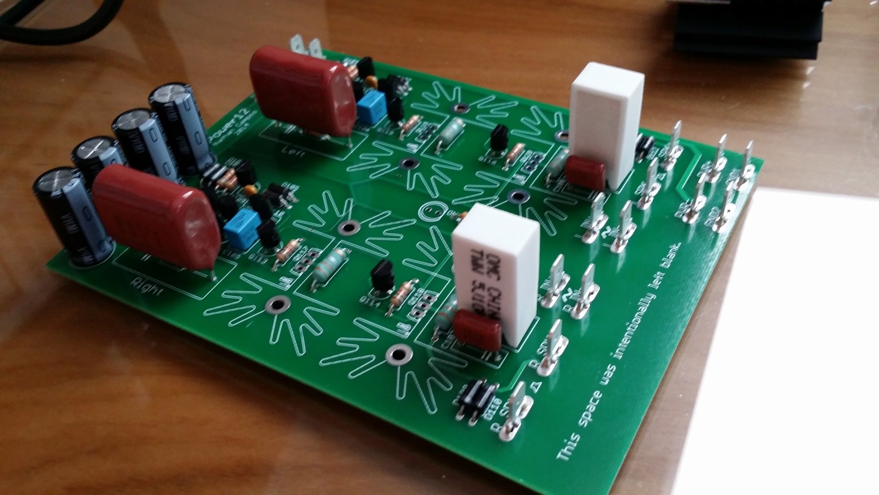
Populating the board was a pretty straight forward process since there aren’t a lot of components to be placed and as usual the most difficult port was soldering the spade terminals to the ground plane.

This time I decided to use a very nice extruded aluminium enclosure that I found on AliExpress. I was a bit skeptical at first about the quality of the enclosures, but when they arrived I was surprised how beautiful they were, and the quality of the extrusion was really good. The seller was great, emailed me to ask about the customs, shipped extremely fast, and packed everything extremely well to make sure nothing would scratch the very fragile black paint of the case and the panels.
Since I decided to use a aluminium enclosure, the best combination would be a very minimalist design, so the only thing in the front panel is the power switch. This decision gave me the idea to place the power LED on the back, giving it a really cool look when it’s powered on.
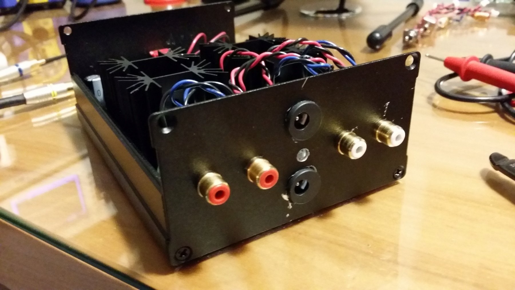
Drilling the holes for the 2.1mm power connectors was a pain in the ass since I didn’t have a drill bit that was bigger than 8mm, so I was forced to use the “wiggle” technique to make the holes bigger and because of that the drill bit escaped the hole a couple of times and damaged a bit of the back plate, but since it’s on the back no one will ever see my mistakes.
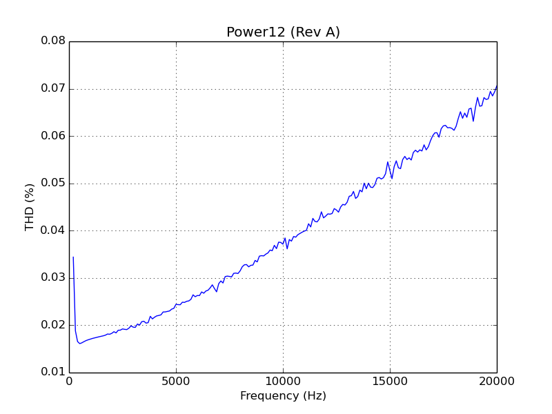
The distortion figures are not the best you’ve probably seen (it’ll be a lot better when I add the second active load in Rev B), but it’s low enough that you won’t be able to notice it. The plot was created using a script I’ve created called plot_thd.py, running this SPICE circuit. Sadly I don’t have the equipment to measure the real figures, but I’m planing to buy a Keithley 2015 next month.
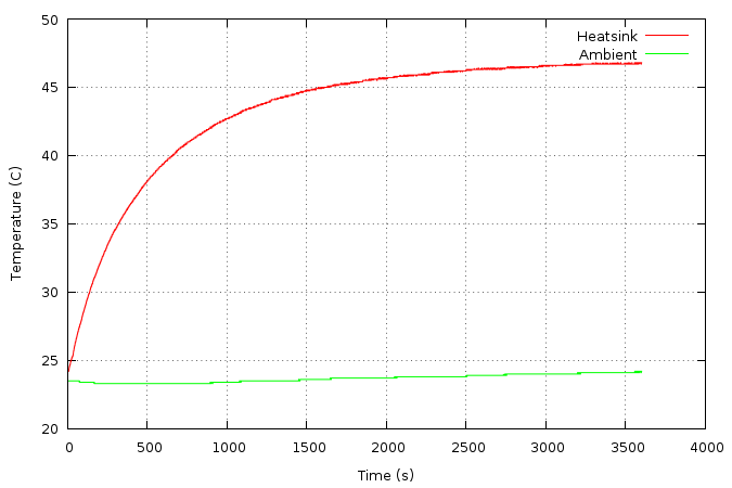
One thing that I actually was able to measure was the temperature profile of the amplifier, and as you can see it runs pretty cool with those FA-T220-38E heatsinks. Those figures were measured with the lid closed and with the amplifier right at the point of clipping with a 1kHz sine wave into a 8 ohm load. I’ve used my Agilent U1242B multimeter in conjunction with a program I wrote called dmmlog to grab the data, then plotcsv to generate the graph you see. Sadly I forgot to take pictures of the test setup.
If you want to see all the pictures of the project this Imgur album contains all of them. If you want to have access to all of the files related to this project check out the GitHub repo, and if you want to discuss it the best place to go would be the diyAudio thread.